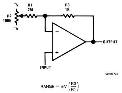
This is known as cross-talk, and it can lead to instability. This load-induced change in supply voltage could then cause changes in the operation of other amplifiers sharing the same supply. If the output stage of a system draws a variable amount of current, the supply voltage could vary. Power supply rejection ratio is a measure of the ability of the op-amp to ignore changes in the power supply voltage. It is desirable to have the CMRR as high as possible. Typical values of the CMRR range from 80 to 100 dB. If the op-amp is ideal, R i and R cm approach infinity (i.e., open circuit) and R o is zero (i.e., short circuit). If the inputs are connected together as in Figure 16, these two resistors are in parallel, and the combined Thevenin resistance to ground is R cm. These are the common-mode resistances, and each is equal to 2 R cm. The model also contains a resistor connecting each of the two inputs to ground. The input resistance of the op-amp, R i, is measured between the inverting and non-inverting terminals. In addition to including input offset voltage, the ideal op-amp model has been further modified with the addition of four resistances. The effects of input offset voltage can be incorporated into the op-amp model as shown in Figure 17. The input offset voltage is obtained by dividing this quantity by the open-loop gain of the op-amp. The output voltage resulting from a zero input voltage is known as the output dc offset voltage. We have altered the idealized model by adding input resistance ( R i), output resistance ( R o), and common-mode resistance ( R cm). 5.2 Modified Op-amp Modelįigure 14 shows a modified version of the idealized op-amp model. The op-amp specification lists the voltage gain in volts per millivolt or in decibels (dB).

Op-amps have high voltage gain for low-frequency inputs. The symbol G is used to indicate the open-loop voltage gain. Voltage gain is a dimensionless quantity. The open-loop voltage gain of an op-amp is the ratio of the change in output voltage to a change in the input voltage without feedback. The actual op-amp has a finite voltage gain that decreases as the frequency increases (we explore this in detail in the next chapter). The ideal op-amp has a voltage gain that approaches infinity. The most significant difference between ideal and actual op-amps is in the voltage gain. As the various parameters are defined in the following sections, reference should be made to Table 9.1 in order to find typical values. We use μA741 operational amplifiers in many of the examples and end-of-chapter problems for the following reasons: (1) they have been fabricated by many IC manufacturers, (2) they are found in great quantities throughout the electronics industry, and (3) they are general-purpose internally-compensated op-amps, and their properties can be used as a reference for comparison purposes when dealing with other op-amp types. Table 1 lists the parameter values for three particular op-amps, one of the three being the μA741.

These parameters are specified in listings on data sheets supplied by the op-amp manufacturer. We begin by defining the parameters used to describe practical op-amps.

Our goal is to develop a detailed model of the practical op-amp – a model that takes into account the most significant characteristics of the non-ideal device. It is important for the circuit designer to understand the differences between actual op-amps and ideal op-amps, since these differences can adversely affect circuit performance. Practical Op-amps approximate their ideal counterparts but differ in some important respects.


 0 kommentar(er)
